PM1v2 Setup Guide – Introduction:
This PM2 setup guide offers two methods to add the device to an ESPHome/Home Assistant instance. You can add a new device and flash the firmware with a physical device connection using the built in USB-C port or you can add it using the pre installed WIFI Captive portal and upload the firmware via OTA. The WIFI Captive portal method is more convenient method since we only need a cell phone etc. to establish your local WIFI connection. If the method chosen is the captive portal then you can install PM1v2 physically in the power distribution panel and complete the configuration remotely using your phone and ESPHome/Home Assistant after one minute of power on time.
In addition to using WiFi as a network transport the PM1v2 is Thread capable. Thread can be configured using one of two methods. Where WiFi exists even with just a two node connection you can use the preloaded captive portal and local web_server file based OTA to install the Thread network component wirelessly or it can be directly flashed using the onboard USB-C port. The prospect of provisioning home automation with ESPHome using a Thread network grants some very appealing capability. It has all the advantages of a Zigbee protocol but is completely standard with a network running on IPv6. ESPhome nodes can be introduced as mesh based nodes but have all the component based functionality. We are not bound to Matter or Zigbee device constraints, we are free to expand the the full set of any available component capability. Keep in mind that all low energy mesh networks like Thread and Zigbee are predominantly implemented with low bandwidth applications.
Important information:
- If you are not familiar with AC mains safety please consult with or hire an electrician to connect the device.
- Never connect to a live AC mains supply during the install.
- Use only appropriately rated mains connection wire. e.g. 18 AWG Flexible AC 300V cord (Item ACCORD3 in the store)
- Always use an non-metallic fire safe enclosure to house the PM1v2. STL files are available for download or the enclosure assemblies can be purchased.
Physical Install:
This guide is not intended to address the physical install as there are to many possible scenarios however please observe the following points.
The hardware manual is available and should be helpful to clarify any physical elements as well.
PM1v2 Hardware Manual :
- Do not install the PM1v2 on the inside of a metal distribution panel as the WIFI signal will be poor do to the shielding.
- Connect CT1 and the AC mains supply to the same same phase line. e.g. Phase A (Mains supply) and CT1 should be paired for accuracy.
- If you are connecting the optional secondary voltage isolation transformer(s) be sure to cut JP4 on two phase units and JP4 + JP5 for 3 phase and connect the AC mains side to same physical phase of the AC line and input CT. Note: If you ordered the PM1v2 with a optional vRef transformer it will be already cut during our free calibration process. (Polarity is not critical for the secondary voltage monitor but it will affect the phase angel data if inverted e.g. phase angle may be negative when you would expect positive.
- CT1 and CT2 (or CT3 if setup for 3 Phase) will detect current in or out of the panel, if you observe a negative current during positive usage then you need to reverse the clamp direction.
- The CT units we sell all have a TVS protection diode and and setup for the onboard 22 Ohm load resistors. If you are using CT’s that that do not meet this specification then you may need to cut JP2 and or JP3 if the CT comes with a load resistor. We recommend using CT’s that are TVS protected for your safety.
ESPhome Builder Home Assistant Add-on is required – see: https://esphome.io/guides/getting_started_hassio.html
The PM1v2 configuration YAML is available from GitHub as a packaged system with preconfigured dashboard import capability. A packaged format provisions improved version control and support. You can still use a completely local YAML configuration as well. All The YAML example files and packages can be accessed here https://github.com/GelidusResearch/grpm2
The PM1v2 ships with a packaged YAML install that facilitates deployment and configuration control when it’s discovered by an Home Assistant instance. When discovered it will be presented with the ESPHome dashboard import card for you to take control and name it as desired. The device will be discovered once it joins the local network. Joining via the captive portal is the simplest way to add it.
Dashboard Import
Here is an example of the discovery presentation on an ESPHome Dashboard.
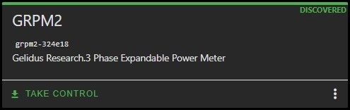
Note: Show discovered devices at the top right … menu must be enabled in the ESPHome builder dashboard to observe the device take control card.
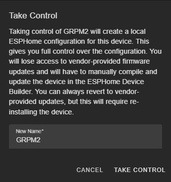
This prompt allows you to add a local device YAML configuration from the discovered PM1v2. This will enable full control of the YAML configuration. It’s the preferred method since you can define all the security attributes of a device and expand it if desired. For a device like the PM1v2 this import is recommended since you will need to maintain the device calibration and other local parameters. You can name it as you wish, short names are recommended and it will be the displayed name. In the background the device name uses the mac address to generate a unique instance.
YAML Files
Configuring the PM1v2 centers on it’s YAML and the options you would like implemented. With a full 18 channel power monitoring set the YAML can be up to 1k lines. To facilitate a manageable YAML file configuration we have pre-configured packages to do most of the basic functions and other that do advanced features. You may not want or need them all enabled thus you can modify them as you required once you have a fully local instance. The grpm2.single.file.example.yaml demonstrates a fully local config with all the channels.
We include base cfg sets such as grpm2.3c.yaml through grpm2.18c.yaml and these YAML files correlate to the installed main board and riser hardware target. The units are pre-configured with them and you can name them as you wish since its more like an example set for getting started with the hardware.
Each pre-configured YAML hosts the dashboard_import component which grants the capability to import and takeover the YAML on your ESPHome Dashboard.
dashboard_import:
  package_import_url: github://gelidusresearch/grpm2/grpm2.6c.yaml@main
import_full_config: trueAll the base YAML files have a substitutions block where we detail the hardware values and other component settings. The main board is common and will have the CT/L designations created, it is recommended to use these for the mains total power monitors. 2 or 3 phase are panel line inputs should be configured at the main board. The main board gains are also included in the substitutions. These are the only current and voltage inputs that will pre-calibrated in the factory. These voltages will be the basis for calibrating other channels since they are all the same phase reference AC inputs. (We can do custom calibration on request of up to 18 channels if you require under 1% accuracy)
substitutions:
  device_name: grpm2
  device_type: ESP32-C6-H4
  device_comment: Power Meter
  disp_name: GRPM2
  update_time: 15s
  line_frequency: 60Hz
  gain_pga: 1X

  # SPI CS Pins
  main_spi_cs_pin: GPIO23
  riser1_spi_cs_pin: GPIO0
  riser2_spi_cs_pin: GPIO1
  riser3_spi_cs_pin: GPIO2
  riser4_spi_cs_pin: GPIO3
  riser5_spi_cs_pin: GPIO10

  # Chip IDs
  main_chip_id: IC1
  riser1_chip_id: IC2
  riser2_chip_id: IC3
  riser3_chip_id: IC4
  riser4_chip_id: IC5
  riser5_chip_id: IC6

  # MainBoard CT and Line Names
  phase_a_ct_name: CT1
  phase_b_ct_name: CT2
  phase_c_ct_name: CT3
  phase_a_line_name: L1
  phase_b_line_name: L2
  phase_c_line_name: L3

  # MainBoard Calibration Values (adjust these for your installation)
  phase_a_voltage_cal: 4200
  phase_b_voltage_cal: 4200
  phase_c_voltage_cal: 4200
  phase_a_current_cal: 14200
  phase_b_current_cal: 14200
  phase_c_current_cal: 14200
  enable_gain_calibration: true
enable_offset_calibration: truePackage YAML files
The package YAML file content acts like overlays that combine content that would otherwise be reported as entry duplicate errors. We can give each package a set of variables which allow a single file like the grpm2.atm90e32.yaml file to combine any similar components configuration requirements thus reducing the duplication of YAML content.
Here we take the substitutions as the top level and add vars to create the individual values a multi instance component may require. You could name them as desired such as Furnace or Dryer instead of CT4 etc.
In this example we are configuring the base functions of the ATM90E32 metering ICs. The advanced features can be added per IC as shown at the end of this YAML.
For more details for these types of options have a look at the provided usage example grpm2.use.example.yaml
packages:
  remote_package_files:
    url: https://github.com/gelidusresearch/grpm2
    files:

#********************************************************
# For advanced configuration options and custom CT grouping examples,
# see: https://github.com/gelidusresearch/grpm2/blob/main/grpm2.use.example.yaml

      - path: packages/grpm2.atm90e32.yaml
        vars:
          chip_id: ${main_chip_id}
          spi_cs_pin: ${main_spi_cs_pin}
          unit_name: MainBoard
      - path: packages/grpm2.atm90e32.yaml
        vars:
          chip_id: ${riser1_chip_id}
          spi_cs_pin: ${riser1_spi_cs_pin}
          unit_name: Riser1
          phase_a_ct_name: CT4
          phase_b_ct_name: CT5
          phase_c_ct_name: CT6
          phase_a_line_name: L4
          phase_b_line_name: L5
          phase_c_line_name: L6
          phase_a_voltage_cal: 4200
          phase_b_voltage_cal: 4200
          phase_c_voltage_cal: 4200
          phase_a_current_cal: 14200
          phase_b_current_cal: 14200
          phase_c_current_cal: 14200

#********************************************************
# Enable advanced power quality features for board(s)

      - path: packages/grpm2.atm90e32.pq.yaml
        vars:
          chip_id: ${main_chip_id}
unit_name: MainBoardNetwork
By far the most common network choice will be WiFi. Attaching to Wifi can be done using the Captive Portal component which is preconfigured. 15 seconds after power up the SSID should be advertised.
Captive portal prep:
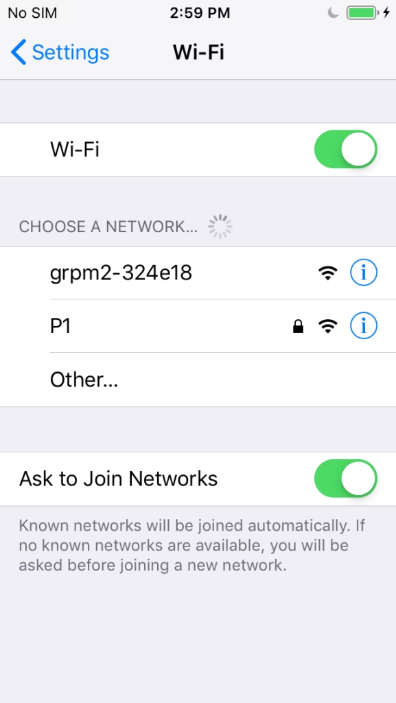
Select the grpm2 SSID. The password is blank and it should redirect you to the web UI. If not use the browser with http://192.168.4.1
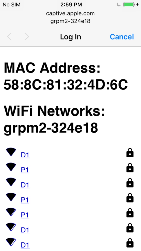
Once you join the captive portal you can select the SSID to join.
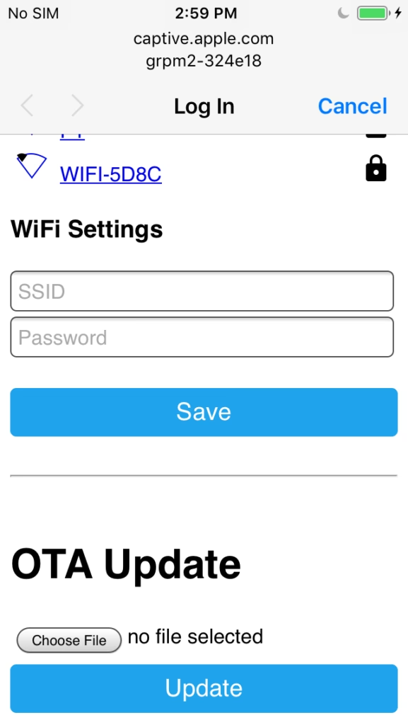
Once the SSID and password are entered be sure to save it. If you typo’d then it will fail after several minutes and will advertise it again.
Take note that you can also compile and upload an OTA firmware image too. You can also directly flash the unit via USB-C.
Once WiFi is successfully connected the unit will send multicasts of it’s device name via mDNS and this will be discovered by HA if it is located on the same IP subnet. If you do not have HA on the same subnet then you may need to find the DHCP IP address on the router to add it manually in HA using it’s IP address.
You should secure your ESPHome device. The following elements are important.
# You Home Assistant API
# The password is a UUID key the is a tool to generate them, this is compiled into the
# firmware and is used by HA to encrypt all data over the net.
#
# https://esphome.io/guides/security_best_practices
#
# Read the BP and configure your esphome secrets file
# Top right on the ESPHome dashboard

api:
  encryption:
    key: "ADC89tJWsIx84Q94VemUGmT9/SgiQLl+LBRjS0X7XG8="

# The OTA password very important too, don't let some one flash you devices
# You can use a key
ota:
  - platform: esphome
    password: "91a704ac3898391a88db7245bd2fe6a2"
  - platform: web_server
# If you have the web based OTA enabled then be sure to set up an admin user and password

wifi:
  ssid: !secret wifi_ssid
  password: !secret wifi_password
  output_power: 20.5
  enable_btm: True
  enable_rrm: True

  # Enable fallback hotspot (captive portal) in case wifi connection fails

  ap:
    ssid: "Gdo1 Fallback Hotspot"
    password: "3Fb8dhZFVIgO"

# Example configuration entry, unfortunately its not SSL capable yet
web_server:
  port: 80
  auth:
    username: !secret web_server_username
password: !secret web_server_password Thread
With the inclusion of Thread capability this next section explains how to get a basic Thread install up and running from scratch.
The simplest and most cost effective way to establish an Thread Mesh network is to use the integrated OpenThread implementation within Home Assistant and ESPhome.
To do this we require an Open Thread Border Router service to run directly on Home Assistant. It also requires a USB dongle to transmit and receive 802.15.4 protocol on the network.
The dongle functions as our 802.15.4 SoC running RCP firmware (Radio Co-Processor)
We also sell one with OpenThread pre-installed. See EFR32MG21 USB Dongle
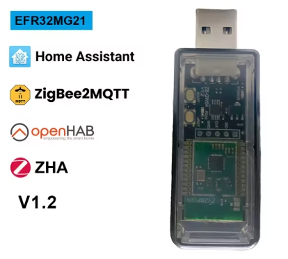
OpenThread RCP firmware can only be properly installed via the SWD port and requires compiling on VSCode. Current ZB-BW04 units like this one from amazon etc will come with Zigbee firmware installed and will not work without the OpenThread RCP firmware build and flash install. Also multi protocol Zigbee/Thread firmware builds are not stable.
These two Open Thread components will form the core of our IPv6 network and will be used to create a secure Thread Mesh Network that the Thread capable ESP32-C6-H4 PM1v2 MCU can connect with.
We connect the USB Dongle directly to the HA host and it communicates with RCP over USB. (Hardware will vary, I use a VMware VM and map the USB port to my HA host in this example)
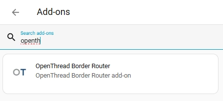
First we add the OpenThread Border Router Add-on in Home Assistant
Setting->Add-ons-> Add-on Store-> Search for “OpenThread”
Install it and open the card.
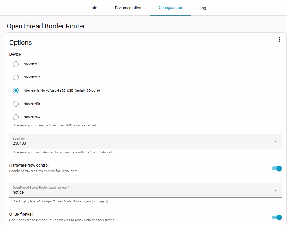
Make sure it’s set to start on boot then select the Configuration menu.
The USB dongle shows up as /dev/serial/by-id/usb-1a86_USB_Serial-if00-port0 on my test bed.
This USB dongle runs the RCP at 230400 baud, be sure to set it and turn the firewall on.( no need to process junk)
Once its connected and running you need to grab the TLV or Type-Length-Value struct from the OT service which encapsulates all the network parameters using a TLV for you to enter on any device node. This allows the PM1v2 device to connect and authenticate on the Thread Mesh Network we have established.
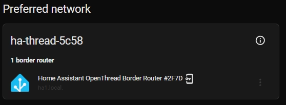
From the Home Assistant Settings-> Integration menu locate the Thread card. Open the entry and view the info.
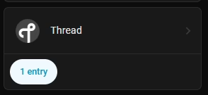
Select 1 entry

Select the gear icon
Select the Info Icon
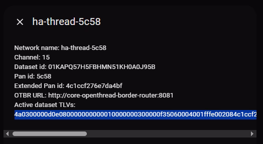
Copy the TLV and edit the GRPM1v2 YAML as shown in this example. We need to remove/comment any Wifi component YAML and the other components which cannot connect via IPv6
#wifi:
#  ap:
#    ap_timeout: 15s

#captive_portal:

#improv_serial:

network:
  enable_ipv6: True

openthread:
  tlv: 4a0300000d0e0800000000000300000f35060004001fffe002084c1ccf276e7da4bf0708fdbfbfa49e5
  device_type: FTD

text_sensor:
  - platform: version
    name: ESPHome Version
    hide_timestamp: true
  - platform: openthread_info
    ip_address:
      name: "Thread IP Address"
    channel:
      name: "Thread Channel"
    role:
      name: "Thread Device Role"
    network_name:
      name: "Thread Network Name"
    pan_id:
name: "Thread PAN ID"Note: Due to WEB formatting issues we could not use the full TLV in the example, YAML requires specific indentation and the TLV code shown here was modified to keep the correct indentation.
This completes the PM1v2 setup guide.