PM1 Setup Guide:
Our PM1 setup guide offers two methods to add the PM1 to an ESPHome/Home Assistant instance. You can add a new device and flash the firmware with a physical device connection via USB serial or you can add it using the pre installed PM1 WIFI Captive portal and upload the firmware via OTA. The WIFI Captive portal method is by far a more convenient method since we only need a cell phone to establish your local WIFI connection. If the method chosen is the captive portal then you can install PM1 physically in the power distribution panel and configure it remotely using your phone and ESPHome/Home Assistant after one minute of power on time.
Important information:
- If you are not fammiliar with AC mains safety please consult with or hire an electrician to connect the PM1.
- Never connect to a live AC mains supply during the install.
- Use only appropriately rated mains connection wire. e.g. 18 AWG Flexible AC 300V cord (Item ACCORD3 in the store)
- Always use an non-metalic fire safe enclosure to house the PM1. (Item PM1BOX1 or PM1BOX2 in the store or 3D print it yourself)
- Do not install the PM1 on the inside of a metal distribution panel as the WIFI signal will be poor do to the shielding.
- Connect CT1 and the AC mains supply to the same same split phase line. (Higher accuracy)
- If you are connecting the optional secondary voltage isolation transformer be sure to cut JP2 and connect the AC mains side to the alternate split AC line. (Polarity is not critical for the secondary voltage monitor)
- CT1 and CT2 will detect current in or out of the panel, if you observe a negative current during positive usage then you need to reverse the clamp direction.
The ESPhome Home Assistant Add-on is required – see: https://esphome.io/guides/getting_started_hassio.html
Captive portal or Physical USB Serial Method prep:
Open the ESPhome add-on menu and add a new device.
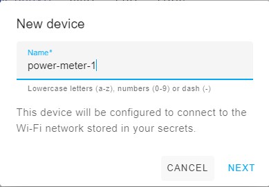
The device name must be unique.
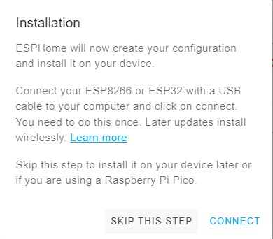
Skip this step. We need to add a full configuration first.
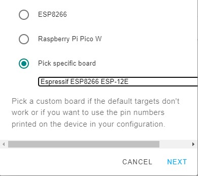
Select the Expressif ESP8266 ESP-12E
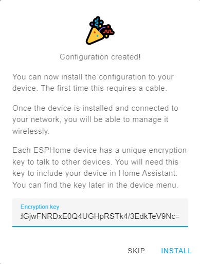
Skip again. Note the generated unique key, this must be preserved in the config going forward.
Edit the newly created device named power-meter-1, preserving the api key, add the example PM1 code after the captive portal line, as shown.
# GRPM1 v1 Setup Guide 2025.10.7
esphome:
  name: power-meter-1

esp8266:
  board: esp12e

# Enable logging
logger:

# Enable Home Assistant API
api:
  encryption:
    key: "YOUR_API_KEY_HERE"

ota:
  - platform: esphome
  password: "YOUR_OTA_PASSWORD_HERE"
  - platform: web_server

wifi:
  ssid: !secret wifi_ssid
  password: !secret wifi_password

  # Enable fallback hotspot (captive portal) in case wifi connection fails
  ap:
    ssid: "power-meter-1"
    password: ""

captive_portal:

web_server:
  port: 80
  version: 3

substitutions:
  # Change the disp_name to something you want
  disp_name: PM1
  # Interval of how often the power is updated
  update_time: 15s
  # Current transformer calibrations:
  # Tuning: adjusted current_cal = current measure/esphome current * current_cal value
  # 100A/50mA SCT-013 with 2x gain: ~15270
  # 200A/100mA SCT-023 with 2x gain: ~27240
  # 200A EARU T-24 with 2x gain: ~13000
  # 120A EARU T-16 with 2x gain: ~20300
  # Tuning: adjusted voltage_cal = voltage measure/esphome voltage * voltage_cal value
  # 120V operation with the Integrated Block AVB 2,0/2/6 Transformer: ~4470
  # 120V operation with GRPM1 AC 120/6V Transformer Kit:  ~4670
  # 240V operation with the Integrated Block AVB 2,0/2/6 Transformer: ~8940
  # 240V operation with GRPM1 AC 240/6V Transformer Kit:  ~9140
  phase_a_current_cal: '15270'
  phase_c_current_cal: '15240'
  phase_a_voltage_cal: '4585'
  phase_c_voltage_cal: '4709'

spi:
  clk_pin: 14
  miso_pin: 12
  mosi_pin: 13

sensor:
  - platform: wifi_signal
    name: ${disp_name} WiFi Signal
    update_interval: 60s
  - platform: atm90e32
    cs_pin: 5
    phase_a:
      voltage:
        name: ${disp_name} L1 Volts
        accuracy_decimals: 4
      current:
        name: ${disp_name} CT1 Amps
        id: "ct1Amps"
      power:
        name: ${disp_name} CT1 Watts
        accuracy_decimals: 1
        id: "ct1Watts"
      gain_voltage: ${phase_a_voltage_cal}
      gain_ct: ${phase_a_current_cal}
      phase_angle:
        name: ${disp_name} L1 Phase Angle
      peak_current:
        name: ${disp_name} CT1 Peak Current
      harmonic_power:
        name: ${disp_name} CT1 Harmonic Power

    phase_c:
      voltage:
        name: ${disp_name} L2 Volts
        accuracy_decimals: 4
      current:
        name: ${disp_name} CT2 Amps
        id: "ct2Amps"
      power:
        name: ${disp_name} CT2 Watts
        accuracy_decimals: 1
        id: "ct2Watts"
      gain_voltage: ${phase_c_voltage_cal}
      gain_ct: ${phase_c_current_cal}
      phase_angle:
        name: ${disp_name} L2 Phase Angle
      peak_current:
        name: ${disp_name} CT2 Peak Current
      harmonic_power:
        name: ${disp_name} CT2 Harmonic Power

    current_phases: 2
    frequency:
      name: ${disp_name} Freq
    line_frequency: 60Hz
    gain_pga: 2x
    chip_temperature:
      name: ${disp_name} IC Temperature
    update_interval: ${update_time}
  - platform: template
    name: ${disp_name} Total Amps
    id: "totalAmps"
    lambda: return id(ct1Amps).state + id(ct2Amps).state;
    accuracy_decimals: 4
    unit_of_measurement: A
    update_interval: ${update_time}
    device_class: current
  - platform: template
    name: ${disp_name} Total Watts
    id: "totalWatts"
    lambda: return id(ct1Watts).state + id(ct2Watts).state;
    accuracy_decimals: 0
    unit_of_measurement: W
    device_class: power
    update_interval: ${update_time}

  - platform: total_daily_energy
    name: ${disp_name} Total kWh
    power_id: totalWatts
    filters:
      - multiply: 0.001
    unit_of_measurement: kWh
    device_class: energy
    state_class: total_increasing

time:
  - platform: homeassistant
    id: homeassistant_time

switch:
  - platform: restart
name: ${disp_name} RestartCaptive Portal Method:
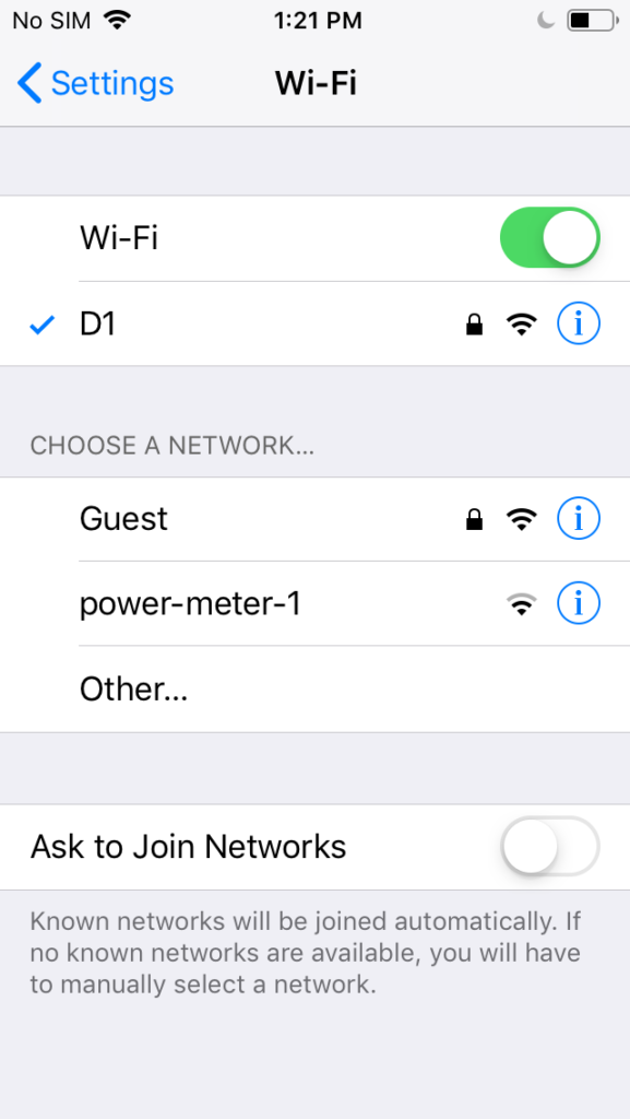
With the PM1 already powered up for at least 1 minute, use a phone or other capable device connect to the PM1 default preinstalled captive portal AP SSID named power-meter-1. Some versions of ESPHome do not auto redirect to the portal. Use http://192.168.4.1 on the device you connected with in those cases.
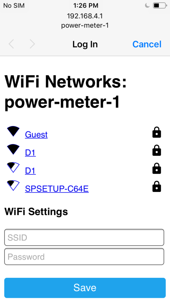
Set the SSID and Password.
After a minute or so visit the PM1 WEB portal using its mDNS address to verify it’s ready. Power cycle it if required.
http://power-meter-1.local
Prepare the firmware by selecting INSTALL on the top right of the ESPHome edit screen.
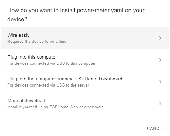
Select wirelessly.

PM1 will now come online and you can add it to Home Assisant with the configured key.
Physical USB Serial Method:
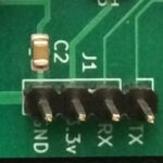
To enable flash mode on the PM1 you need to depress and hold SW1 then connect your USB to serial adapter to the uart flashing connector as shown here. Once power is applied the button can be released and PM1 will be in flash mode. (Preconnecting J1 and then plugging in the USB end is usually easier)
Serial TX and RX pins should be crossed e.g.
J1 PM1 :    USB Adapter
TX     ->   RX
RX     <-   TX
3.3v   -    3.5v Max
GND    -    GND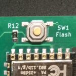
Prepare the firmware by selecting install on the top right of the ESPHome edit screen.
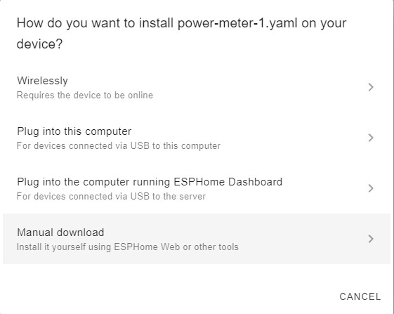
Select Plug into this computer.
PM1 will now come online and you can add it to Home Assisant with the configured key.
This completes the PM1 setup guide.