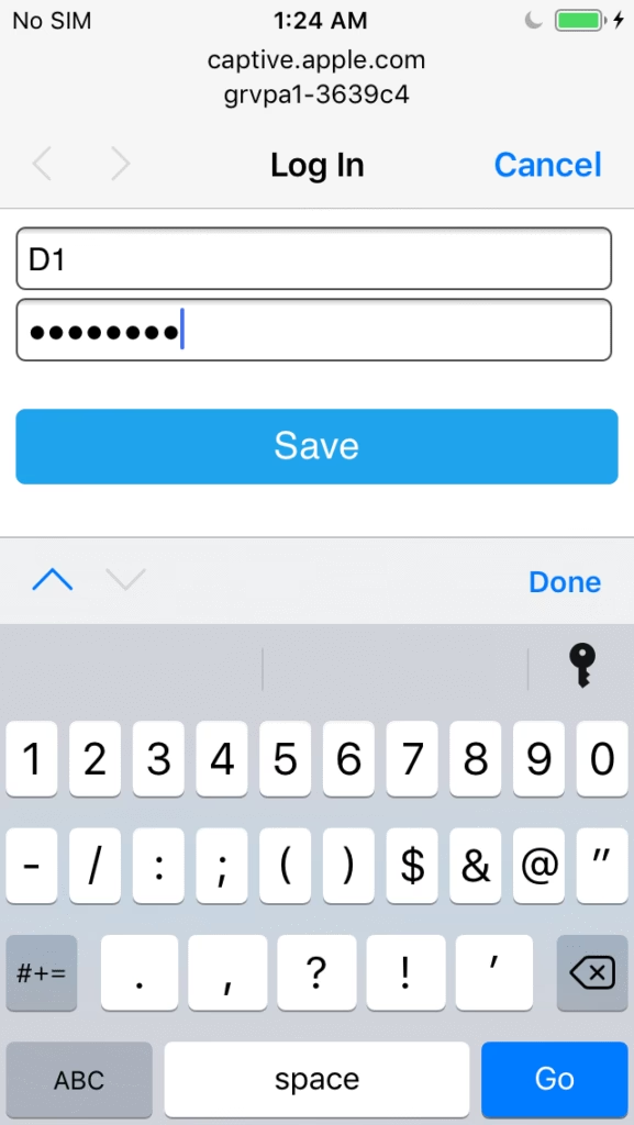
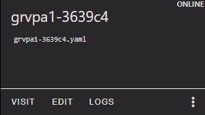
The GRVPA1 can be added to Home Assistant or operated as a stand alone device using its ESPHome pre installed WEB UI. Using the local WEB UI simply requires joining WiFi via the captive portal. The unit will advertise a captive portal name of grvpa1-xxxxxx where xxxxxx is a portion of the esp32’s unique MAC address. Be sure to record the device name to use for accessing it one it’s connected to your WiFi network. Here is a walk through of a captive join for the device named grvpa1-3639c4

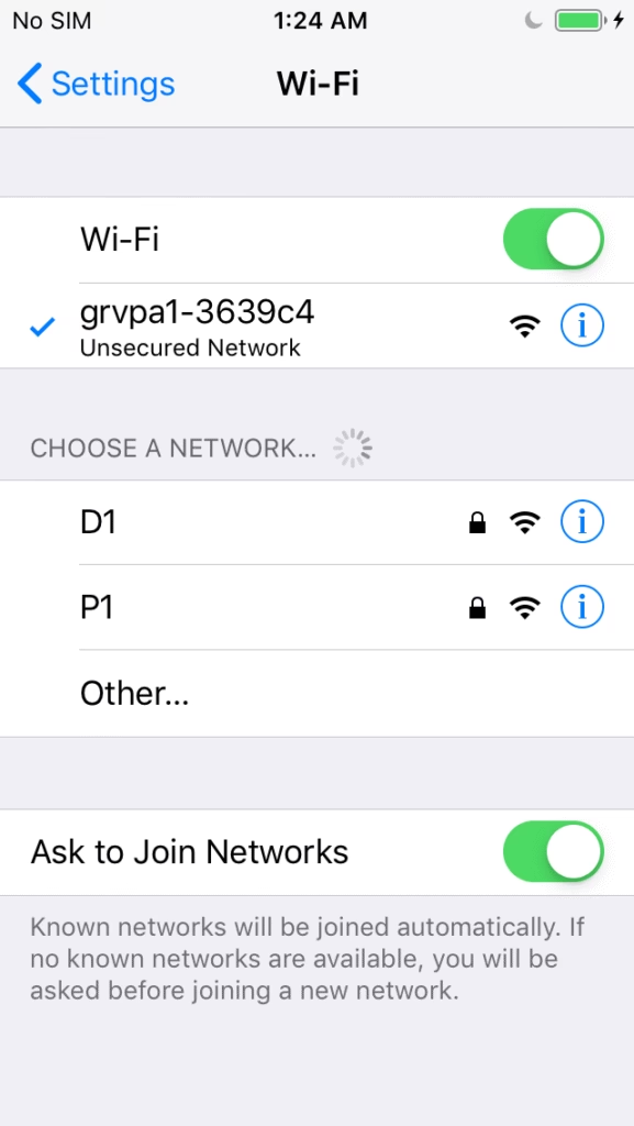
Once the GRVPA1 is joined to your local WiFi network you can access it from a mDNS advertised URL. Note: mDNS is usually available but not in all cases, if not, you need to find the DHCP address of the device from your local router and use that instead.
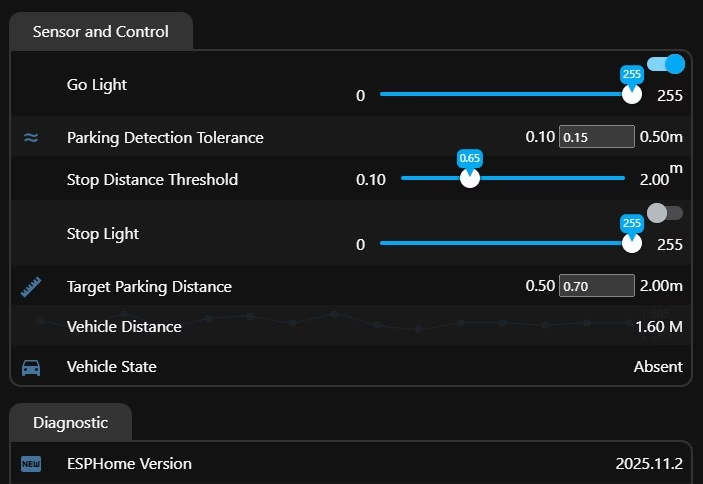
Navigate to unique device name e.g. http://grvpa1-3639c4.local the WEB UI should be presented.
Set the stop distance threshold for your environment. The unit will always be green unit the threshold is breached where it will transition to red. You should approach slowly giving the GRVPA1 time to sense the changes.
The lights are automatically controlled and cannot be permanently altered. You can omit or include the parking state sensing for HA with a package file include from the GelidusResearch repo https://github.com/GelidusResearch/grvpa1 to use it in you need to add the grvpa.state .vx.yaml file content.
A dashboard import would automatically include the config.
ESPHome and Home Assistant Integration
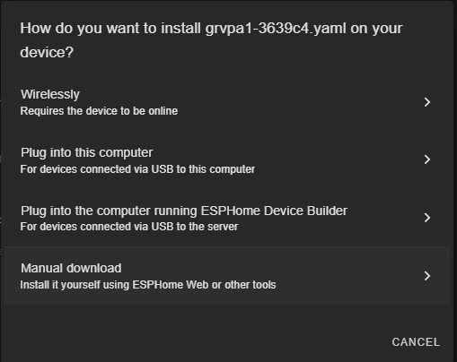
ESPHome integration is inherently available on HA however simply adding a discovered ESPHome device does not give you secured full control of it. If there is need to modify the device in any way it must be added to HA using the ESPHome Builder Add-On by one of the available methods. We ship the unit with a discoverable YAML that is integrated with ESPHome’s dashboard import capability. We also offer a method that allows you to manually create the YAML. You can chose to import and take over the device or perform the full YAML device creation and editing. Discovery requires using the device captive portal to connect your WiFi.
This dude explains it well: https://www.youtube.com/watch?v=0t12tRsphlM
The following process will add the GRVPA1 in fully managed mode you will be able to generate and update new firmware for the device. Please note that any error in passwords etc. can force a direct flash recovery. On the AC powered unit it will require a USB to UART adapter which we can provide but if your careful that’s rarely ever an issue.
Note for your safety: Flashing the ESP32 on an AC model must be done with a 3.3v supply on a USB-TTL adapter and never when connected to an AC supply.
On a USB-C unit you can just connect it on a PC and flash it directly for recovery or any other purpose.
Requirements:
- The ESPhome Builder Add-on is required – see: https://esphome.io/guides/getting_started_hassio.html
- The ESPHome secrets.yaml file must be configured – very important since the device YAML uses this file.
- Refer to: https://esphome.io/guides/yaml/#secrets-and-the-secretsyaml-file
- File editing can be launched from the top right corner of the builder dashboard.
- Backup any ESPHome device YAML text in case you need to refer to any auto generated password if something goes wrong.
ESPHome Builder is an HA management console that parses YAML text for instructions to compile the various ESPHome components and functions for a firmware image that runs on our hardware devices. To add a device we need to create it’s YAML instruction set for the target device instance and it’s network environment. Most of this is abstracted using the ESPHome Builder console.
- We create device names and device type criteria around it
- We generate the API interface to talk with HA
- We add an OTA service to update the firmware from ESPHome Builder.
- We set WiFi network credentials to allow network access.
- We add component configurations.
- Once the install runs, all these elements are processed in the backend ESPHome subsystem
- We flash the device with one of many available methods.
Physical Install
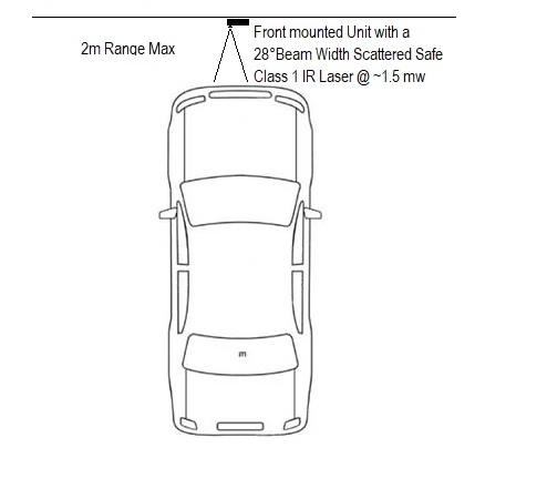
Direct the beam using the swivel mounted sensor focused downward to the front of the vehicle.
ESPHome Device Preparation
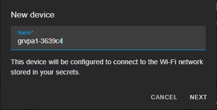
We add the device name, to make life easy use the current pre-flashed one.
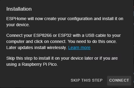
Skip this step, we will be using WEB UI file OTA upload method to flash the device.
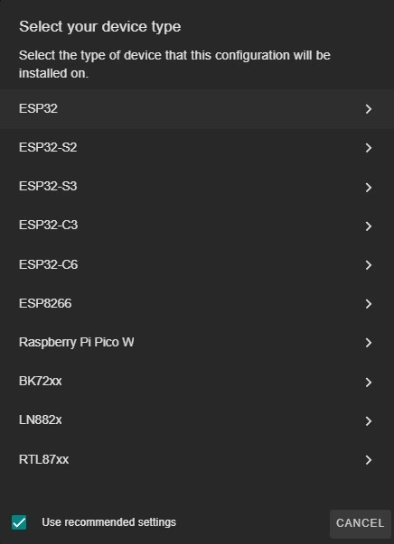
The GRVPA1 is powered with an ESP32 as shown so we need to set it likewise.
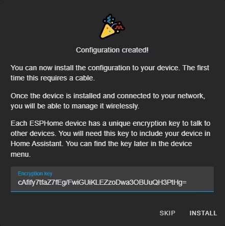
Skip this step and note the generated unique key, this must be preserved in the config going forward.
Now we can edit the newly created device yaml file grvpa1-3639c4.yaml preserving the API key etc, add the example content code after the captive portal line, as shown and edit the noted elements in the example comments.
We should see this auto generated bare minimum device YAML.
esphome:
  name: grvpa1-3639c4
  friendly_name: grvpa1-3639c4

esp32:
  board: esp32dev
  framework:
    type: esp-idf

# Enable logging
logger:

# Enable Home Assistant API
api:
  encryption:
    key: "cAfify7tfaZ7fEg/FwiGUiKLEZzoDwa3OBUuQH3PtHg="

ota:
  - platform: esphome
    password: "aac47812833fe20f10dd8ad7c8a1f946"

wifi:
  ssid: !secret wifi_ssid
  password: !secret wifi_password

  # Enable fallback hotspot (captive portal) in case wifi connection fails
  ap:
    ssid: "Grvpa1-3639C4 Fallback Hotspot"
    password: "x3WriQVGJt52"

captive_portal:Example GRVPA1 YAML Configuration
esphome:
  name: grvpa1-3639c4
  friendly_name: GRVPA1 # Or what ever you like

esp32:
  board: esp32dev
  framework:
    type: esp-idf

# Enable logging
logger:


# Enable Home Assistant API
api:
  encryption:
    key: "<your_key>" # use the auto generated key here

# Edit OTA to match the auto genereated values
ota:
  - platform: esphome
    password: "<your password>"  # recommened but can be ommited for testing
  - platform: web_server         # File based web ui upload - factory image default

wifi:
  power_save_mode: none
  ssid: !secret wifi_ssid          # Check the secrets file for the correct values
  password: !secret wifi_password  # Ditto

  # Enable fallback hotspot (captive portal) in case wifi connection fails
  # Don't set the SSID it will use the device name dynamically
  ap:
    password: !secret captive_password # Add this new entry to your secrets file
    ap_timeout: 20s

captive_portal:

safe_mode:

web_server:
  port: 80
  version: 3
#  username: !secret web_user      # enable for minimal security
#  password: !secret web_password  # needs secrets file entries created first

i2c:
  id: i2c_bus1
  sda: GPIO16
  scl: GPIO17
  scan: true

output:
  - platform: ledc
    id: pwm_red_output
    pin: GPIO25
    frequency: 500 Hz
    inverted: false
    max_power: 0.40
  - platform: ledc
    id: pwm_green_output
    pin: GPIO26
    frequency: 500 Hz
    inverted: false
    max_power: 0.40

number:
  - platform: template
    name: "Stop Distance Threshold"
    id: stop_distance_threshold
    min_value: 0
    max_value: 2.0
    step: 0.1
    restore_value: true
    initial_value: 0.5
    unit_of_measurement: "m"
    optimistic: true

light:
  - platform: monochromatic
    name: "Stop Light"
    output: pwm_red_output
    restore_mode: ALWAYS_OFF
  - platform: monochromatic
    name: "Go Light"
    output: pwm_green_output
    restore_mode: ALWAYS_ON


sensor:
  - platform: vl53l0x
    id: tof1
    internal: true        # Keep data local
    address: 0x29
    timing_budget: 200ms
    update_interval: 250ms
    long_range: true

    filters:
      - quantile:
          window_size: 4
          send_every: 1
          quantile: .9

    on_value:
      then:
        - lambda: |-
            static float last_good = -1;
            float dist = id(tof1).state;
            float stop_thresh = id(stop_distance_threshold).state;

            // Reject invalid readings
            if (dist <= .1 || dist > 2) {
              id(pwm_red_output).set_level(0.0);
              id(pwm_green_output).set_level(0.40);
              return;
            }

            // LED logic
            if (dist <= stop_thresh) {
              id(pwm_red_output).set_level(0.40);
              id(pwm_green_output).set_level(0.0);
            } else {
              id(pwm_red_output).set_level(0.0);
              id(pwm_green_output).set_level(0.40);
            }

  - platform: wifi_signal # Reports the WiFi signal strength/RSSI in dB
    id: wifi_signal_db
    update_interval: 60s
    entity_category: "diagnostic"
  - platform: copy # Reports the WiFi signal strength in %
    source_id: wifi_signal_db
    name: "WiFi Signal Strength"
    filters:
      - lambda: return min(max(2 * (x + 100.0), 0.0), 100.0);
    unit_of_measurement: "%"
    entity_category: "diagnostic"
    device_class: ""


status_led:
pin: GPIO23Once the YAML is ready you can install it on the WiFi connected device using a WEB UI file upload. This will require we manually download the firmware using the browser and then connect to the WUB UI using http://grvpa1-3639c4.local and then select the file to upload from there. The reason we do this method is to allow for password and name differences that may exist on the device. for example if the OTA password is set in YAML and it is changed the OTA would not work. Also if the name is changed it will not work because it uses the mDNS resolve to find the device IP.
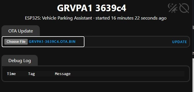
File type should be OTA format when prompted for it.
Physical USB Serial Method
To enable direct flash mode on the GRVPA1 AC model you need to depress and hold the flash button then toggle the reset button. Make sure you connect your USB to serial adapter to the UART flashing connector as shown here.
Serial TX and RX pins should be crossed e.g.
J1 GRVPA1 : USB Adapter
TX       ->    RX
RX       <-    TX
3.3v      -    3.5v Max
GND       -    GND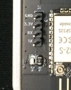
For the USB-C powered model just simply connect the cable, the flash mode will auto enable.
Prepare the firmware by selecting install on the top right of the ESPHome edit screen.
Select Plug into this computer.
GRVPA1 will now come online and you can add it to Home Assistant with the configured key.
This completes the setup Guide.